Flashing ESP8266 module ESP-01 in Manjaro (Arch Linux) and a story of Serial Port under Linux
17 Jun 2020, 06:41pm TZ +05:30
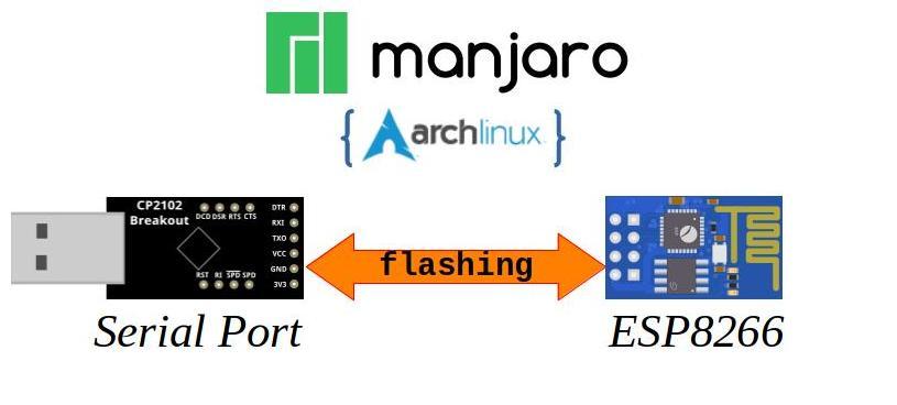
Let’s look at how to use Serial-Port under Manjaro (Arch-Linux) . Our goal would be to flash a ESP8266 chip . More specifically the tiny module ESP-01 .
This may be out of time in the 2020.
I wanted to fix the serial-port issues once and for all.
Here goes my quest to simplify serial-port logging & debugging on Linux.
1. ESP-01 Module #
It’s been some time since my last adventure with ESP8266.
Things have advance much further. ESP-01 remains to be cheapest of the WiFi modules.
Here is a link to ESP-01 specification in PDF from the original company Ai-thinker :
http://wiki.ai-thinker.com/_media/esp8266/docs/a001ps01a2_esp-01_product_specification_v1.2.pdf
Source : ESP8266 Community Website
1.a Buy ESP-01 #
ESP-01 is a very widely used module. It can easily be bought locally in Bharat (India).
Here are some of the usual places :
- https://robokits.co.in/iot-internet-of-things/esp8266-wifi-serial-module-esp-01-for-iot-applications
- https://robu.in/product/esp-01s-esp8266-wifi-module/
- https://www.amazon.in/s?k=esp-01
2. Serial Port - CP2102 USB Dongle - USB to TTL #
In the past I have used CP2102 for my serial port needs. It has proven time and again to be a useful chip. There are no driver issues in any version of Linux. Many small development boards also come with this chip.
The CP2102 USB to UART Bridge provides a complete plug and play interface solution that includes royalty-free drivers. This USB 2.0 compliant device includes 0 digital I/O pins and is available in a 5x5 mm QFN28 package.
Source : Silabs
This is one of my favorite modules for CP2102:

The reasons for this board’s optimality :
- All Serial port pins brought out to header
- CP2102 pins are inherently 3.3V input but 5V tolerant
- Both 3.3V (100mA only) and 5V available
- Breadboard friendly pin-out.
Lately this board has become scares. There are new improved alternatives also available. Here we would be using this board. The similar connections can be followed on other Serial-port boards also.
2.a Buy CP2102 Black Board #
Currently very few places sell these local in Bharat (India):
- https://robu.in/product/cp-2102-6-pin/
- https://www.amazon.in/CP2102-Module-Converter-Replace-Techleads/dp/B07N69V5CR/
Still many of the shops in local electronics markets do carry these.
2.b Possible Alternatives #
Here are few alternatives for these serial port boards:
FT232Rl
- https://www.amazon.in/eHUB-FT232RL-Module-3-3V-Mini/dp/B07MNX233C/
- https://robokits.co.in/arduino/motor-control-boards/interface-boards/ft232rl-ftdi-usb-to-ttl-serial-adapter-module
- https://robu.in/product/ft232rl-usb-to-ttl-5v-3-3v-download-cable-to-serial-adapter-module-for-arduino/
- Note: For these board you need to make sure that the Level is set to 3.3V. Else the connected devices might get damaged.
3. Serial Port in Linux #
Typically all the devices in Linux are just files.
Serial ports are not any different.
3.a The Devices #
Typical Serial Port devices under Linux :
/dev/ttyUSB0= Typically for any USB-Serial converter chips like CP2102, FT232, PL2303, CH340 .etc. Depending on the number of devices attached one can havettyUSB1,ttyUSB2and so-on./dev/ttyACM0= Typically for any emulated USB-Serial devices. Such asUSB-CDCdrivers on various development boards. Similar to the normal chip based USB-Serial, when multiple of such devices are connected the numbering becomesttyACM1,ttyACM2and so-on. Examples of such devices areST-LINK/V2-1 with serial-link enabled Nucleo boards,Arduino Zero (Native USB).etc.
3.b Serial Port parameters #
Apart from the device name there are many parameters that govern the serial port operation.
These come from the legacy of RS232 lineage.
BAUD rate= Speed of communication. Typically measured bits-per-second. Some of the typicalBAUD ratesare9600,14400,19200,38400,57600,115200and more. Most of the times than not9600and115200are the common values that one comes across. Some devices use odd ballBAUD rateslike ESP8266 which has a default speed of74880instead of the defaults. Typically all theseBAUD rateswere are derivative of a crystal frequency11.0592MHzor3.6864MHz.Data Bits= Number of bits sent in one go. Typically its8-bitsor1 Byteper character transmitted over serial. Again other values like5,6and7are for legacy reasons. We would use8for most cases.Stop Bits= These are used to indicate the pause or end of one character transmitted over serial port. Typically1-bitis sufficient for our purposes.Parity="Odd"or"Even"or"None": This is an error checking bit that’s generated by counting number of1s in the character begin sent. Typically we would keep it as"None".Handshake="Hardware"or"Software"or"None": This is a way of synchronizing communications between two serial port devices. We use these synchronization signalsRTS,DTRfor other purposes. Hence the"None"would be our choice.
3.c Serial Port Physical interface #
Another important distinction is the signal voltage level. Here are the various voltage levels :
- RS232 standard levels : +15V to -15V max.
- RS422 standard levels : +25V to 0V max.
- RS485 standard levels : +24V to -24V max.
- TTL-5V RS232C levels : +5.5V to 0V max.
- TTL-3V RS232C levels : +3.3V to 0V max.
Typically the TTL-5V and TTL-3V are the only ones supported in the USB-Serial converters
are talking here. Among them our focus would be on the TTL-3V for CP2102 board discussed
earlier.
3.d Permission for Serial Port access under Linux #
In order to access the Serial port one requires permissions.
Typically under Manjaro (Arch Linux) a user needs to be a member of uucp and lock groups.
| |
After adding the user to the groups one needs to reboot the computer.
For more information on how to use Serial Ports and permission under Manjaro (Arch Linux):
https://wiki.archlinux.org/index.php/Working_with_the_serial_consoleIn case of Ubuntu or Debian Linux based systems the group is called as dialout:
| |
4. Tools for Serial Port in Linux #
There may be a plethora of tools out for Windows. On Linux side there only a few. Though one can argue that, our focus is on Embedded application use. Not the generic one. Hence we need some specialized tools.
Here are list of few tools for Embedded logging, debugging activity use in Manjaro (Arch Linux) :
4.a picocom - minimal terminal emulation program
#
The program
picocom
is a Linux terminal program. It sets up the communication with
the desired Serial port with the chosen settings.
Inside the picocom terminal control can be initiated usingCtrl + a key combination.
Its also called the Escape character.
Here are list of useful shortcuts using Ctrl + a before:
Ctrl + x= Exit thepicocomprogramCtrl + t= ToggleDTRline on the Serial PortCtrl + g= ToggleRTSline on the Serial PortCtrl + b= Change Baud rate of the serial portCtrl + h= Show the Key shortcuts
For more insight visit:
https://linux.die.net/man/8/picocomInstall picocom
#
For Manjaro (Arch Linux):
| |
For `Ubuntu or Debian Linux:
| |
Use picocom
#
On the shell to initiate picocom write:
| |
This would open a terminal for /dev/ttyUSB0.
The set baud rate would be 115200 using the -b option.
The additional --imap lfcrlf helps to convert the Linux Terminal
<LF> or \r into <CR>+<LF> or \r\n.
4.b moserial - GNOME Serial terminal program
#
This is gtk based serial terminal for logging and file capture.
For all those liking GUI better than the Terminal.
Though the project is in beta state, the program is very well functional.
https://sourceforge.net/projects/moserial/
However this does not have capability to control RTS and DTR signals.
Also it only supports Standard Baud rates. In our case we need custom
Baud rate if we want to talk to ESP8266.
Install moserial
#
For Manjaro (Arch Linux):
| |
For `Ubuntu or Debian Linux:
| |
4.c ESPlorer - ESP8266 IDE for Lua and MicroPython
#
This is combined tool targeted to ESP8266 users.
It contains an IDE for editing both LUA and MicroPython code.
In addition it supports the AT command firmware commands.
For more information and Download visit:
Here is UI:
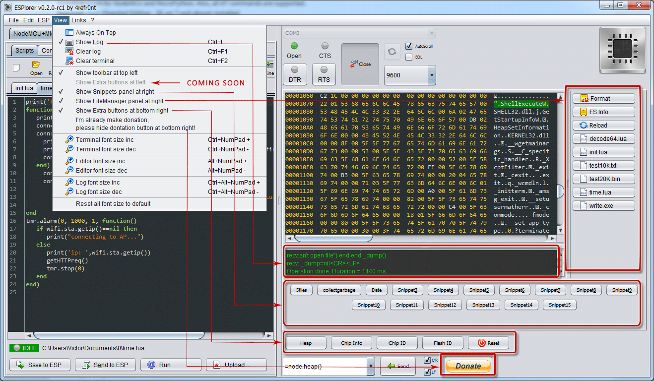
Source: ESPlorer project
This is very useful and preferred:
- It has independent control for
RTSandDTRsignals - Support for ESP8266 specific and general
Baud rates.
Hence we would be using this.
Please note that this needs JDK to be installed prior to running it.
Download ESPlorer
#
Download this file:
http://esp8266.ru/esplorer-latest/?f=ESPlorer.zipThen Extract it in a desired location creating the ESPlorer folder.
Running ESPlorer
#
In a terminal run the following:
| |
5. Connecting CP2102 Board to ESP8266 module ESP-01 #
Let’s now look at how we can connect the CP2102 Black Board and ESP8266 module ESP-01.
Here is a representative schematic:

Here is a Table showing the actual connections:
| S. No | CP2102 Black Board | ESP8266 Module ESP-01 | Color |
|---|---|---|---|
| 1 | 3V3 | VCC | Red |
| 2 | GND | GND | Pink |
| 3 | RXI | TXD | Blue |
| 4 | TXO | RXD | Green |
| 5 | DTR | GPIO0 | Cyan |
| 6 | RTS | EN / CH_PD | Brown |
Here is the Pin-outs of both the boards :

Double check the wiring before plugging in the USB connector.
5.a Insight into the Wiring #
Well you might wonder why we did the wiring this way. There are reasons.
- TX to RX connection is logical, since Input to Output mapping is needed for any communication channel.
- Power pin VCC to 3V3 connections - we need 3.3V for the ESP-01 to work.
- Ground forms the reference.
- The other two pins
CH_PDandGPIO0follow the directive from :esptoolrecommendations
For more details of ESP8266 Boot Mode selection:
https://github.com/espressif/esptool/wiki/ESP8266-Boot-Mode-Selection6. Using Arduino to flash ESP-01 module via CP2102 Board #
With our circuit in place, we have a programming setup.
Let’s first try to test out our setup with Arduino
6.a Install ESP8266-Arduino Board Package #
In order to do so first we need the ESP8266-Arduino Board package installed.
https://github.com/esp8266/ArduinoWe need to add URL in the Arduino:
- Open
File => Preferences => Additional Board Manager URLs: - In the field
Additional Board Manager URLs:click on the button at the end. It would open a window called"Additional Boards Manager URLs". - Enter the path to the
ESP8266-Arduino Board package:https://arduino.esp8266.com/stable/package_esp8266com_index.json - Click on
"OK"in the"Additional Boards Manager URLs"window - Again click on
"OK"in the"Preference"window to save the configuration. - Next Open Board Manager from
Tools => Board:"...." => Boards Manager... - Type
ESP8266in the search box. This would bring up the ESP8266 Arduino package. - Click on “esp8266” and then click on
"Install"to begin the installation. - Watch the lower bar for completion of the process
- After completion click on
"Close"to exit the Board Manager.
6.b Load the Blink example #
Now that we have the ESP8266 Arduino install, we can begin programming the ESP-01.
Lets first select the correct ESP8266 board.

Next make sure that the board configuration is correct.

In case the default selections are incorrect, make sure to correct them as show above.
Make sure that the correct Serial port is selected.
Load the Blinky Example from
File => Examples => ESP8266 => Blink

The Blue LED on the ESP-01 board should now start blinking.
7. Using esptool to flash ESP-01 with AT Firmware
#
esptoolA Python-based, open source, platform independent, utility to communicate with the ROM bootloader in Espressif ESP8266 & ESP32 chips.
esptool.pywas started by Fredrik Ahlberg (@themadinventor) as an unofficial community project. It is now also supported by Espressif. Current primary maintainer is Angus Gratton (@projectgus).
Source :
esptool repo at Github
It’s an advanced tool for programming ESP8266. Internally Arduino in the
earlier step
also uses esptool.
7.a Install esptool
#
Typically there are two ways :
- Via the
Python Package installerorpiphttps://pypi.org/project/esptool/ - Via the Linux package management
For Manjaro (Arch Linux):
| |
For Ubuntu or Debian Linux:
| |
Its better to install using pip in Ubuntu or Debian Linux.
Since they have older versions.
7.b Download the AT Firmware #
We need to obtain the AT Firmware from Espressif website:
https://www.espressif.com/en/support/download/atDownload the latest version of ESP8266 NonOS AT Bin Vx.y.z.
At the moment its V1.7.4.
Extract this into a folder, and keep the path handy.
Typically the bin directory is all we want for flashing.
7.c esptool commands
#
Let’s check if we can actually perform some communication with ESP8266 using esptool
Fetch Chip ID of the ESP8266 in ESP-01 #
| |
Fetch the Flash Chip ID #
This also tell us the size of the Flash chip.
| |
This confirms our communication with ESP8266 in the ESP-01 module.
7.d Flashing the ESP-01 with AT Firmware #
First go to the bin directory in the extracted AT Firmware.
And execute the command.
| |
Output:
| |
That’s It ! we are now ready to test out the AT Firmware.
7.e Insight into the flashing command #
Before we test out the AT Firmware let’s take a deeper look at the command. It would enable you to prepare your own commands in the future.
As per the official documentation
# BOOT MODE
## download

### Flash size 8Mbit: 512KB+512KB
    boot_v1.2+.bin              0x00000
    user1.1024.new.2.bin        0x01000
    esp_init_data_default.bin   0xfc000
    blank.bin                   0x7e000 & 0xfe000
In our case we have the following files in bin directory:
blank.bin= Empty blockboot_v1.7.bin= Bootloader which is equivalent toboot_v1.2+.binesp_init_data_default_v08.bin= Initialization Data for ESP8266 AT Firmware. Equivalent toesp_init_data_default.bin.- Next,
at\512+512directory which represents the 1MB memory broken into 2 blocks. There we find theuser1.1024.new.2.binas needed.
Apart from the names, the document also provides us with the desired addresses where the specific files need to loaded.
From the looks of it we know write_flash would initiate programming.
Hence the command becomes:
| |
8. Testing AT Firmware on ESP-01 using ESPlorer
#
Run the ESPlorer as instructed earlier.
It would connect directly. The default setting is good enough.
Switch to the AT-based tab on the left and click on big "Open" button.
8.a AT command Response for checking communications
#
Then press the AT command button in the Basic AT Commands section.
It should be something like this.

If the board returns OK upon sending the AT you have communication!.
Your AT Firmware on ESP-01 is running correctly.
8.b AT+GMR command response for AT Firmware Version
#
Let’s now look at the version of the AT Firmware using AT+GMR command.
AT+GMR
AT version:1.7.4.0(May 11 2020 19:13:04)
SDK version:3.0.4(9532ceb)
compile time:May 27 2020 10:12:17
Bin version(Wroom 02):1.7.4
OK
Here is how it looks like.

8.c More AT Firmware Commands #
There are various commands to perform WiFi connection, discover networks and various other things.
For more documentation refer to:
- https://www.espressif.com/en/products/sdks/esp-at/resource
- https://docs.espressif.com/projects/esp-at/en/latest/
- https://github.com/espressif/esp-at
9. Success At last ! #
Yes, now you know :
- How to use Serial Port under Linux
- What are the tools available that are Embedded application friendly.
- How to connect ESP8266 module ESP-01 for programming.
- How to install and use Arduino ESP8266 Board package
- How to use advanced tools like
esptoolto flash AT Firmware
This was quite insightful for me as well. Discovering so many things.
This time we breached the 700 line marker.
Hope that this article helps you in getting started with ESP8266 and understanding Serial Ports under Linux a little better.
Let me know if you have any problems or suggestions : DM me on Mastodon .